Designing for Accuracy

This tip has been written for CorelDRAW® Graphics Suite X5. While similar features might be available in previous releases the tutorial will be fully applicable to CorelDRAW Graphics Suite X5 only.

What you will learn
In this tutorial you will learn how to use
Dimensioning lines
Segment Dimension lines
Call-outs
Connector lines

CorelDRAW has the power and the flexibility to allow you to create even the most detailed of drawings or designs with ease and accuracy. From straight forward call-outs to dimensioning lines that offer ten decimal place accuracy.

Working with Dimension Lines
CorelDRAW allows you to easily add various types of dimensioning lines and call-outs. By using dimension lines, you can indicate the distance between two points in a drawing or the size of objects. By default, dimension lines and the measurements shown on the lines change when you change an object’s size. This is referred to as dynamic dimensioning and can be very useful if you need to resize an object or group of objects and want to avoid having to recreate the dimensioning lines.

There are four dimension line tools, parallel vertical / horizontal, angular and segment. The Parallel dimension tool allows you to draw dimension lines on any angle. To draw a parallel dimension line, click the Parallel dimension tool in the toolbox. To draw a vertical or horizontal dimension line, open the Dimension tools flyout by clicking the arrow in the bottom-right corner of the Parallel dimension tool button in the toolbox, and click the Horizontal or Vertical dimension tool button.
• Click to place the starting point, and drag to where you want to place the endpoint of the dimension line.
• Move the pointer to position the dimension line, and click to place the dimension text.
By default, dimension text is centered on the dimension line, however this can be changed in the interactive property bar.

To draw a vertical or horizontal dimension line, open the Dimension tools flyout by clicking the arrow in the bottom-right corner of the Parallel dimension tool button in the toolbox, and click the Horizontal / Vertical dimension tool button.
• Click to place the starting point, and drag to where you want to place the endpoint of the dimension line.
• Move the pointer to position the dimension line, and click to place the dimension text.

To draw an angular dimension line, click the arrow in the bottom-right corner of the Parallel dimension tool button to open the Dimension tools flyout, and click the Angular dimension tool.
• Click where you want the two lines that measure the angle to intersect, and drag to where you want the first line to end.
• Click where you want the second line to end.
• Click where you want the angle label to appear.

Creating Segment Dimension lines
To draw segment dimension lines, in the toolbox, click the arrow in the bottom-right corner of the Parallel dimension tool button to open the Dimension tools flyout, and click the Segment dimension tool.
• Click the segment that you want to measure.
• Move the pointer to where you want to position the dimension line, and click where you want to place the dimension text.

With the Segment dimension tool, you also have the ability to measure the distance between the two most distant nodes in multiple segments. Using the Segment dimension tool , marquee select the segments, drag to position the dimension line, and click where you want to place the dimension text. You can also measure successive segments automatically by clicking the Automatic successive dimensioning button on the property bar, and marquee select the segments that you want to measure. Drag to the location where you want to place the dimension text and release.

As we have previously mentioned, you can set how dimension lines are displayed. For example, you can specify dimension units, style, and precision as well as add a prefix or suffix to the dimension text. You can also set default values for all new dimension lines that you create.

We have also stated that by default, dimension text is dynamic. If you resize the object to which a dimension line is attached, the dimension text is updated automatically to display the new size. These properties are set from the interactive property bar that is accessible when you have one of the dimensioning tools selected.

To be able to use connector, callout, and dimension lines with precision, you need to snap them to specific nodes in objects. For more information about snapping and snapping modes, see "Snapping objects" in the CorelDRAW help file

Creating Call-outs
Call-outs can be easily created to identify parts of a drawing or to draw attention to specific parts of a design.

In the toolbox, click the arrow in the bottom-right corner of the Parallel dimension tool button to open the Dimension tools flyout, and click the 3-Point callout tool.
• Click where you want the first callout segment to start, and drag to where you want the first segment to end.
• Click where you want the second segment to end. A text cursor is displayed at the end of the callout line, indicating where to type a label for the object.
• Type the callout text.

You can also change the callout style and the distance between the leader line and the callout text. This is done from the interactive property bar.


Connector Lines
You can draw connector lines between objects. Objects stay connected by these lines even when you move one or both objects. Connector lines, which are also known as "flow lines", are used in technical drawings such as diagrams, flowcharts, and schematics. For information about drawing flowchart shapes, see "Drawing predefined shapes" in the CorelDRAW help file.

There are three types of connector lines that you can draw. You can draw a straight connector line. You can also draw right-angle connector lines with a sharp corner or a rounded corner. You can edit connector lines by moving, adding, or deleting segments.


Using the controls on the property bar, you can modify the width and style of a connector line as well as apply arrowheads. You can also change the color of connector lines. For more information about Formatting lines and outlines, see "Formatting lines and outlines "in the CorelDRAW help file.

With the new tools that have been added it is easy to see how accurately you can create your designs and to convey this information to the viewer.

The Curve Tools

Drawing objects in Corel DRAW is accomplished by using a variety of tools found in the Toolbox. In this Tutorial, we will look at the Curve Tool Flyout. The curve tools include: the Freehand tool, the 2-Point Line tool, the Bezier tool, the Artistic Media tool, the Pen tool, the B-Spline tool, the Polyline tool, and the 3-Point Curve tool. Once properly mastered, the use of these tools will make design creation simple and accurate.

What you will learn

In this tutorial you will learn about:
  • Types of nodes;
  • The Curve Tools, including;
    Freehand tool
    2-point line tool
    Bezier tool
    Artistic Media tool
    Pen tool
    B-Spline tool
    Polyline tool
    3-point curve tool.

Controlling Nodes

Before looking at the various curve tools available in CorelDRAW, we must look at the types of nodes that can be created, and how they are controlled. The figure below shows what a node would look like if selected with the Shape tool. The Shape tool is the standard tool for moving an manipulating nodes. This node pictured is what a cusp node would look like.


Cusp Node
Cusp nodes let you create sharp transitions, such as corners or sharp angles, in a curve object. You can move the control handles in a cusp node independently of one another, changing only the line on one side of the node.

Smooth Nodes
With smooth nodes, the lines passing through the node take on the shape of a curve, producing smooth transitions between line segments. The control handles of a smooth node are always directly opposite one another, but they may be at different distances from the node.

Symmetrical nodes
Symmetrical nodes are similar to smooth nodes. They create a smooth transition between line segments, but they also let you give lines on both sides of a node the same curve appearance. The control handles of symmetrical nodes are directly opposite each other and at an equal distance from the node.

Line Nodes
Line nodes let you shape curve objects by changing the shape of their segments. You can make a curved segment straight or a straight segment curved. Making a straight segment curved does not noticeably change the segment’s appearance, but it displays control handles that you can move to change the segment’s shape.


Now that we understand the various types of nodes in CorelDRAW, we can look at the tools used to create objects and then look at how to modify these objects by adding nodes and using the various types of nodes to make the necessary adjustments. For the purpose of this tutorial, we will only be looking at the freehand tool. While there are a number of other tools available, we will save them for future tutorials that will allow us to better focus on them.

Drawing lines
Now we can move on to the various curve tools available in CorelDRAW. The Curve Tool Fly-out that lets you create both curved and straight line segments.

Freehand and Polyline tools
The Freehand tool lets you control the smoothness of the curved line you are drawing as well as add segments to an existing line. However, the Polyline tool is easier to use for quickly drawing a complex line that consists of alternating curved and straight segments and allows you to draw in preview mode..

2-point Line tool
You can draw straight lines by using the 2-point line tool. This tool also allows you to create straight lines that are perpendicular or tangent to objects.

Bezier and Pen tools
The Bezier and Pen tools let you draw lines one segment at a time by placing each node with precision and controlling the shape of each curved segment. The Pen tool gives you the added ability to preview the line segments as you are drawing.

Artistic media

The Artistic media tool provides access to the Brush, Sprayer, Calligraphic, and Pressure tools.

B-spline tool

The B-spline tool lets you draw curved lines by setting control points that shape the curve without breaking it into segments.

3-point Curve tool
The 3-point curve tool lets you draw simple curved lines by specifying their width and height. You can use this tool to create arc shapes quickly without manipulating nodes.

Now let's see how the Freehand tool works.

For this design we will use the Freehand Tool, which is the first one within the Curve Flyout.

We are going to use a this tool to show how easy it is to recreate a logo from a low resolution (72dpi) bitmap.

Select the Freehand tool and we will start by doing a single left mouse click on the top of the letter "C" of our logo as indicated by the letter "A". Next, double left click on the top right corner then follow around the straight edges, double clicking as you go. A single left click will end it off. Recreate the path as indicated below.

Once the object has been created, select the 4 nodes on the left side vertical lines with the shape tool. Next, on the Interactive property bar, select the Convert to Curve icon.


This will then allow you to use the shape tool to drag the control handles out to match the curvature of the image below.


Once you are satisfied with the shaping of the path around this character, give it a solid contrasting Colors, this way it is easier to see your progress. You can then move on to the next character.

When creating a character or object that is made up of multiple paths or areas that need to be "knocked out" such as in the letters A,a, B,b, D,d, O,o P,p Q,q or R remember that the objects need to be combined once they have been created. This can be done from the Arrange menu and select Combine, once both objects have been selected.

Using this process you will find it easy to re-create almost any image you wish. Some may take a bit more time than others, but in the end, you will have a piece of artwork that will remind you just how easy it is to recreate in the CorelDRAW Graphics Suite.

Drop Shadows 2

9. In the layers palette click the eye icon on the type layer to make it visible. Then press "V" to activate the Move Tool. With the shadow layer still active click the down arrow 3 times and the right arrow 3 times.

shadow09.gif

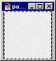
10. Open the background image. In this case, it is the background image of this web site (paper.gif). Press Ctrl-A (Windows®) or Cmd-A (Mac®) or click Select > All. Next click Edit > Define Pattern.

shadow10.gif

11. Add a new layer underneath the existing two layers and make this new layer the active layer. Then click Edit > Fill and choose Use "Pattern" with an Opacity of 100%, Normal mode. Save the file.

At this point you can export it as a JPEG image. The remaining steps are to setup the image for export as a GIF.

shadow11.gif

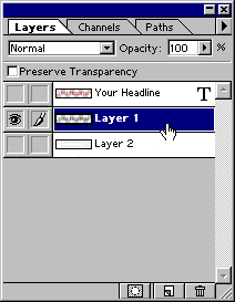
12. In the Layers palette Alt-Click (Windows) or Option-Click (Mac) the eye icon next to the shadow layer. This will make only the shadow layer visible. Then click the mouse on the layer to make it the active editing layer.

shadow17.gif

13. Using the Magic Wand Tool, with a tolerance setting of 0 and no anti-aliasing, click anywhere in the transparent area where there are no pixels. This will select everything on the layer that doesn't have any pixels.

shadow12.gif

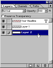
14. In the Layers palette click the other two eye icons to make all the layers visible, then click the bottom layer to make it the active layer.

shadow14.gif

15. Make sure the selection surrounds all the visible pixels of the type layer and its shadow (click here for why this is done).

shadow13.gif

16. Press the Delete key to clear the excess background pixels.

shadow15.gif

17. Click Select > Deselect. This is what the image looks like with the excess background pixels trimmed away.

At this point you can export it as a GIF image.

shadow16.gif

Drop Shadows 1

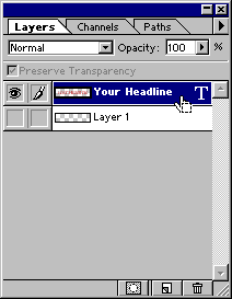
1. First setup the image with a transparent background. Create the type layer that will have the drop shadow applied to it. This automatically inserts a new layer.

shadow01.gif

2. In the Layers palette Ctrl-Click (Windows®) or Cmd-Click (Mac®) the mouse on the type layer. This will select all the pixels on the layer in the shape of the type. Notice the shape of the cursor curspsd5.gif (143 bytes) .

shadow02.gif

3. This is what the layer looks like when selected.

shadow03.gif

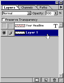
4. Click the eye icon to hide the type layer, then click the empty layer underneath to make it the active editing layer.

shadow04.gif

5. This is what the image looks like on the empty layer with the selection.

shadow05.gif

6. Click Select > Feather. In the dialog, enter 3 to feather the selection 3 pixels.

shadow06.gif

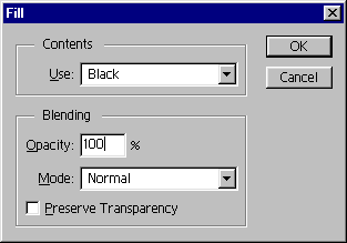
7. Click Edit > Fill. Then choose Black with an Opacity of 100%, Normal mode.

shadow07.gif

8. This is the effect of the fill command. This shadow image lies directly under the type so we need to offset it down and to the right. Before doing so, click Select > Deselect.

shadow08.gif

There are other variations to the shadow effect. You can use Select > Expand to expand the selection, then Edit > Fill with solid black, then use Filter > Blur > Gaussian Blur.